


 |
||||
|
In order to determinate the appropriate slinging method of technical aspects need to be considered: 1. The position of the support points within the truss B. Slinging shall be applied in the node points. if slinging is applied within 10 cm from the node the full load a maximum of 2000kg for TD-Q29S,TD-Q39S-series C. Trusses without vertical end braces must be treated with utmost care. These trusses must always be supported at a node point.
B. In a closed grid or a ground supp0rt, trusses can rotate much more difficult. a corner block or sleeve block prevents them from doing so. In those situations other slinging methods can be used as used as well. C. In case of tilting trusses or truss grids. suspensions are subject to changing forces due to the shift of the point of gravity of the load. For these applications we advice to wrap all chords
B. For trusses with an alternating diag0nal pattern such as the TRINITY TD-Q29S.TD-Q39Sseries, a slinging method where all chords are wrapped - 1 quarter the full node to node distance - fulfils all demands. This method guarantees that the slinging is never attached between node points. B. At intermediate supports of a multiple supported truss, the truss subject to bending moments as well shear forces. Suspending the truss on that position by only slinging two of the main chords (e.g. a lifting bracket), adds an additional bending moment to the main chords. Furthermore the support reaction in these intermediate points is much higher. this shall all be minimised in its possible effect. therefore we advise a slinging method which wraps chords.
Slinging of truss may only be applied in - or close to - the node points preferable support should be at the lower chords as a result of risk reduction actions taken. |
||||
 |
 |
|||
|
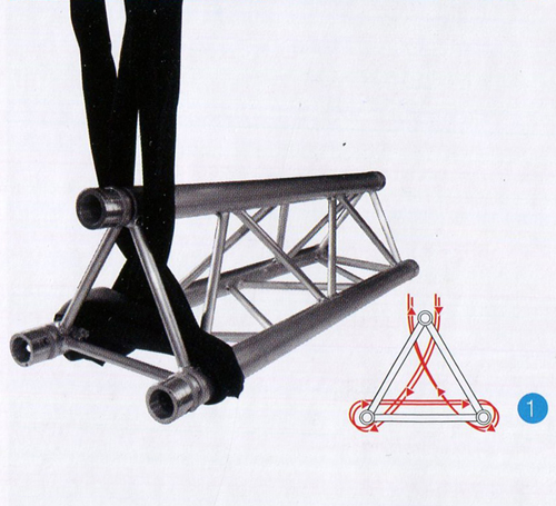
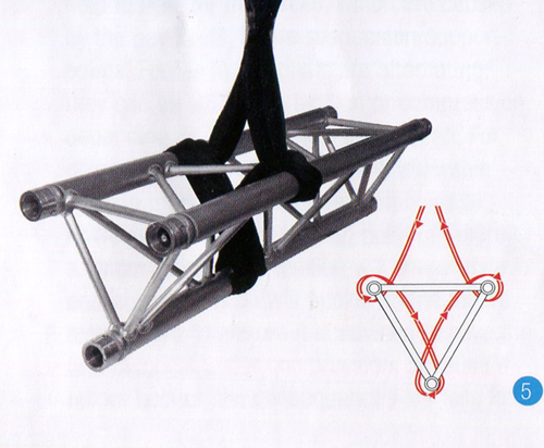
TRIANGULAR TRUSS APEX UP 1 SLING BASKET
|
TRIANGULAR TRUSS APEX UP 1 SLING BASKET
|
|||
 |
 |
|||
|
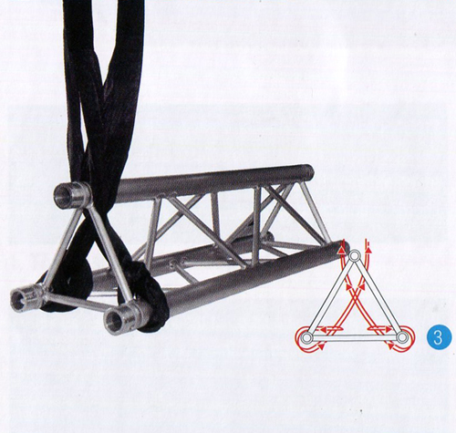
TRIANGULAR TRUSS APEX UP 2 SLING CHOKE
|
TRIANGULAR TRUSS APEX DOWN 2 SLING CHOKE
|
|||
 |
 |
|||
|
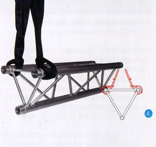
TRIANGULAR TRUSS APEX DOWN 1 SLING WRAP
|
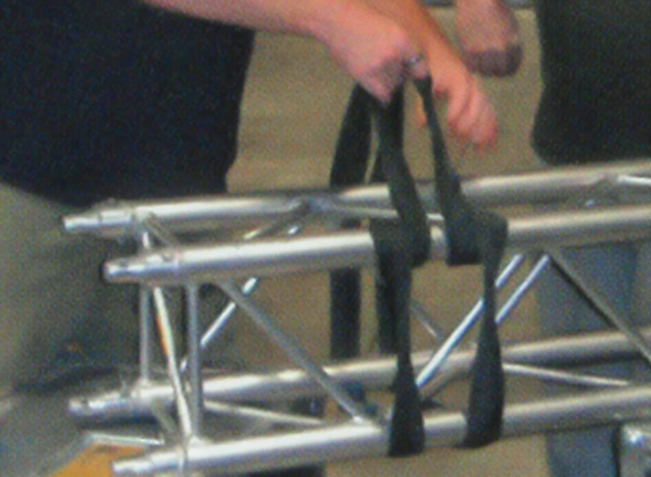
RECTANGULAR TRUSS 2 SLING CHOKE LOWER CHORDS
|
|||
 |
 |
|||
|
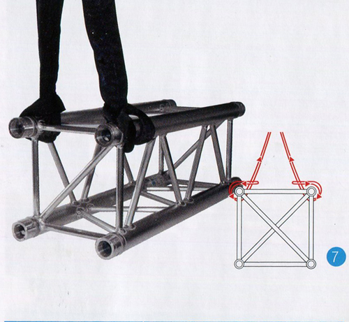
RECTANGULAR TRUSS 2 SLING CHOKE UPPER CHORDS
|
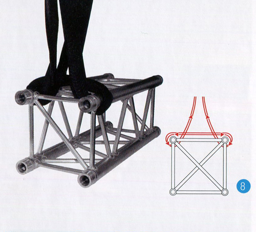
RECTANGULAR TRUSS 1 SLING WRAP UPPER CHORDS
|
|||
 |
.jpg) |
|||
|
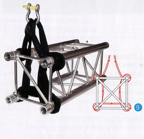
RECTANGULAR TRUSS 1 SLING OPEN WRAP LOWER CHORDS/EXRA WRAP UPPER CHORDS
|
RECTANGULAR TRUSS 1 SLING OPEN WRAP LOWER CHORDS/EXRA WRAP UPPER CHORDS
|
|||
| 21, Xia Mao New Industrial District,Shi Jing Town, Bai Yun District, Guangzhou | 020-86086867 020-86086558 | info@hktrinity.cn | 020-86086827 | ||||
| Copyright 2014 TRINITY TECHNOLOGY LTD. All rights reserved SN:Y.ICP.B. 13006920 Technical Support: Trend Interactive Media | |||||||
 |